
Automatic Printer Calibration: Update
MatterHackers adds automatic height calibration and bed leveling.
Update: Be sure to check out our new article MatterControl - Automatic Print Leveling. This new solution is all software, you will not need to change any hardware or firmware. It will work today.
Hey everyone, here is the promised update to our first post about our work on automatic bed height calibration and leveling. In that post we showed a working implementation of custom firmware gathering data on the level of the print bed and then automatically compensating its movements. Since then we've been working to put the final pieces in place in order to have a full solution that can be used in day-to-day 3D printing. Now, with two printable parts (a z-probe and a modified x-carriage), some magnets, and a switch, it is possible to add automatic bed height calibration and leveling to a Mendel90.
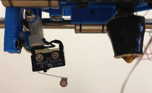
Z-Probe on X-Carriage
No humans required
MatterHackers RepRap Mendel90 Preparing to Printing with Auto Calibration and Bed Leveling
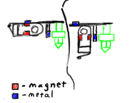
Z-Probe Initial Napkin Sketch
As described in the initial post, our goal with this project was to implement automatic calibration and leveling in a way that would be simple to implement and require no special ongoing interaction with the machine itself. Which is why most of the heavy lifting is being done within the firmware. On the hardware side of things, we were specifically looking to avoid a solution that would require manually lowering the z-probe. With that in mind we modified the G29 command (our bed-leveling command, as mentioned in our first post) so that when G29 is sent at the beginning of a print, the printer will automatically lower the z-probe, probe the bed and then raise the z-probe.
Here is a quick run down on what we actually did:
-
Designed parts for a z-probe and a z-probe mount.
-
Added the z-probe mount to the mendel90's x-carriage. To do this we took the scad file for x-carriage, opened it and then pasted in our z-probe mount at the bottom.
-
Installed the modified x-carriage with z-probe. The z-probe attaches to the mount using an M3 screw.
-
Installed a small screw onto the back wall, behind the x-carriage so that we can push on it to raise and lower the z-probe.
-
Wrote the movement paths to lower and then raise the z-probe.
-
Compiled all the code together and loaded it onto our mendel90.
-
Added the new G29 (new probe bed instruction) just under the G30 (home all) in slic3r custom gcode section, and processed an STL file.
Do Try This at Home
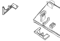
Z-Probe Detail Drawing
For the intrepid adventurers who want to test this solution out themselves, here is everything you will need:
Resources
- Modified Marlin Firmware With Auto Leveling
- The Parts on Thingiverse
Hardware
1x Printed x-carriage
1x Printed z-probe-mount
1x Printed up-down-bar
5x 2.5m x 12m socket head cap screws
1x 3m x 25m socket head cap screw
4x 3m washers
1x 3m nyloc nut
1x mechanical limit switch
2x 10mm x 5mm x 3mm neodymium magnets (ours came from a sonicare brush head)
Step-by-step Guide
- Print out the new x-carriage, z-probe-mount and up-down-bar.
- Press the magnets into the holes on the x-carriage.
- Attach the limit switch to the z-probe-mount with 2x 2.5m x 12 screws
- Attach the up-down-bar to the z-probe-mount with 2x 2.5m x 12 screws and put on nuts.
- Attach the z-probe-mount to the x-carriage with the 3m x 25 screws placing a washer after the screw head, between the carriage edge and the probe edge on both sides, and before the nyloc nut.
- Put the new mount on you mendel90.
- Drill a 2.2mm screw hole into your mendel90 frame, 9mm from the left inside cut out and 5mm above the bottom of the cut out. This will hold the raising and lowing pin.
- Insert one 2.5m x 12 screw into the raising and lowering pin hole.
- Hook up the z-probe switch to the z-min switch connection.
- Add a G29 to your slic3r custom g-code config just after the G28 (home all axis).
You will also need to configure the offset to the extruder in the firmware (Auto_Bed_Level branch) for you exact printer.
The offset of the z-probe can be found in configuration.h, starting at line 201 it looks like this:
define X_EXTRUDER_OFFSET_FROM_Z_PROBE 35
define Y_EXTRUDER_OFFSET_FROM_Z_PROBE -14
define Z_EXTRUDER_OFFSET_FROM_Z_PROBE 7.10
- You can calculate these values with this procedure:
- With the z height correctly set (this is just normal reprap step), position the extruder exactly on the bed
- Run a m114 and record the result
- Move the x and y (in proterface) to put the probe in the same x and y position the extrude is in then run a g30 (do a sigle probe)
- Run another m114 to find the probe position and height and record the result
- Subtract the first m114 from the second m114 and enter the values into the configuration.h
Currently this is only set up to work with RAMPS boards. If you have another board, you will have to get the z-bed switch working on the z-min switch for your printer. If you do, we would love to have your patch.
Have fun printing,
Lars.
More Videos
MatterHackers RepRap Mendel90 Extends and Retract a Z Bed Height Probe
MatterHackers RepRap Mendel90 Printing with Dynamic Bed Leveling
MatterHackers RepRap Mendel90 Printing on Unlevel Bed