
How to 3D Print a Map of Anywhere in the World
Roy (aka "The SmithBot") presents us with a hands-on guide to turning your neighborhood, city, state, or favorite National Park into a 3D printable topographic map.
A few months ago my friend Barney said, “Can you 3D print Thousand Palms Canyon?”
I knew what he meant: all the hills and gulleys and landscape features we’re familiar with. “No,” I said. “That’s impossible.” But the idea kept bugging me. Why not? So I did what any of you would do in the middle of a sleepless night: I went online. Huh! Not impossible, but maybe a little bit tricky. Below are the step-by-step instructions to create a 3D topographic map.
Author's Note: I’m using Photoshop and 3DS Max on a PC to edit files and export them to my MakerBot Replicator 2, so this procedure might be different for you if you’re using other software. I bet it will be similar enough for this info to be useful, though.
Update (May 2016): There has been a piece of software developed to assist in the STL map generating tool. The link for the free STL creator is here: http://jthatch.com/Terrain2STL/. The original article is below and produces a higher resolution STL, if that is needed.
1. Download and install Google Earth.
2. Download and install MicroDEM - a free application available through the U.S. Naval Academy website. Install involves two steps - download and run the installer first, then replace the executable with the latest version (available as a separate download).
3. Download and install the srtm4.1 plugin for Google Earth (Note: clicking on this link may automatically download the srtm4.1 plugin, depending on your browser).
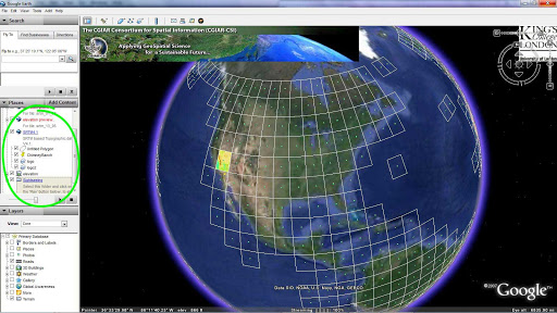
A. Selecting a topographic region in Google Earth
4. In Google Earth, the SRTM4.1 will appear under “My Places” in the navigation on the left. Click on the small “Elevation” square, and a grid of boxes should appear on the globe image (Image “A”);
5. Click on one of the boxes that includes topography you want to print;
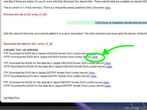
B. Topographic data - download options
6. A window will appear (You might need to scroll down). Click on the link as in Image “B”;
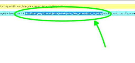
C. Topographic data - the direct download url
7. The auto-download probably won’t work, so copy the url as suggested, and paste it into your browser, as shown in Image “C.” This download may take a few minutes;
8. Unzip the downloaded archive. The only file you need is the .asc file. Put it somewhere you can find it easily. Toss the rest;
9. You need to use MicroDEM to interpret the altitude data. (Don’t try using any of the other “helpful” tools on the Internet to open this kind of file – some of them are nasty viruses!);
10. In MicroDEM, go to File>Open>Open DEM and locate your file;
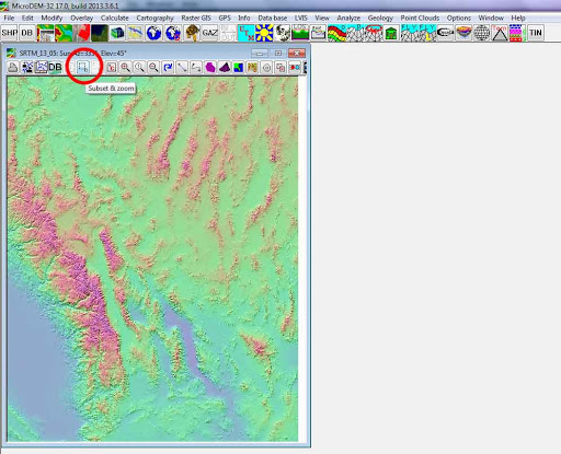
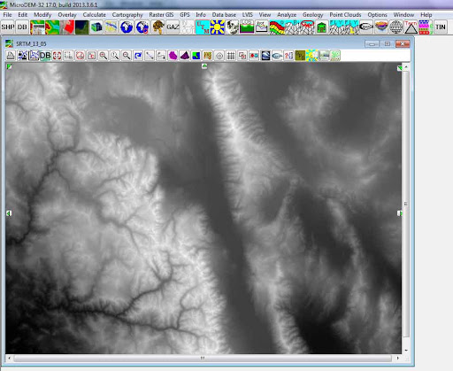
D. Using MicroDEM to preview your topographic data
11. Here’s the tricky part: You probably have no idea what you’re looking at. No highways, no names of cities, no identifiers of any kind! So you’ll need to reference back-and-forth with some other map to narrow down the area you want to print. When you figure out which part of the map you want to zoom in on, use the “Subset & zoom” tool (dotted border) from upper left to lower right to zoom in (Image “D”);
12. Right-click on the map and choose “Legends/marginalia,” and make sure none of the boxes is selected (don't forget to remove the gridlines);
E. Exporting topographic data in greyscale
13. Right-click again, select Display parameter>Elevation>Gray scale. This is the image you will use in your 3D program to create a displacement map in order to print your topographical 3D model (Image “E”);
14. Select File>Save image, and choose whatever image format works best in your 3D program (I use jpeg);
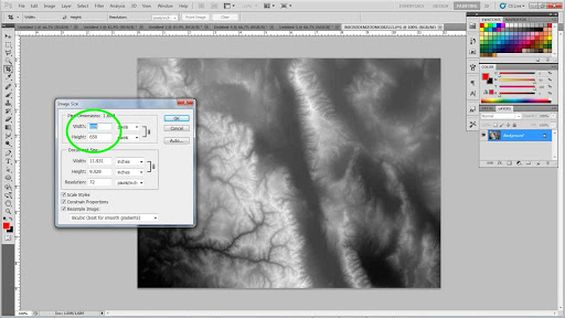
F. Checking the image size in Photoshop
15. Quit out of MicroDEM and open Photoshop or whatever image-editing program you use. Open the file you just saved. Check to determine image size, and jot it down. Mine happened to be 860x650 pixels. That means, when I create a plane object in 3DS Max it will be, like, 8.6in x 6.5in or 860mm x 650mm or whatever units you prefer (Image “F”). Close the file;
Editor's Note: If you don't have Photoshop there are plenty of other options for checking the dimensions of an image. In Windows Explorer single-clicking a picture file will display the dimensions in the info panel at the bottom of the window.
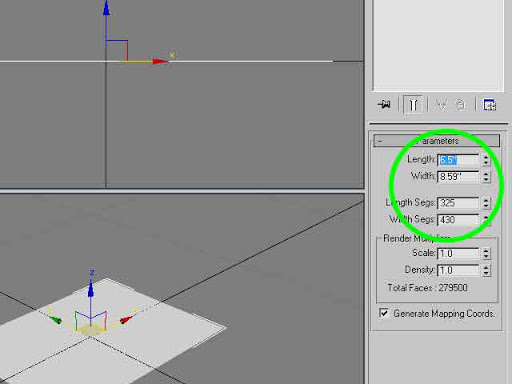
G. Creating a plane in 3D Studio Max
16. Open your 3D program, create a plane with similar dimensions (You might need to switch width for length), and give that plane LOTS of segments, like, 430x325. I divided dimensions in half (Image “G”);
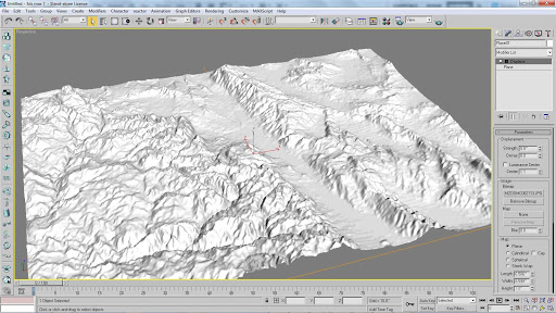
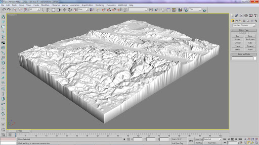
H. Creating a displacement map from your grayscale elevation image
17. In 3DS Max (or whatever you’re using), select the plane, go to the Modifier List, scroll down to “Displace,” and add your grayscale map to create the terrain you want. Adjust “strength” to exaggerate the height of the mountains however you prefer. Problem is, a plane has only two dimensions, so you can’t print it with a 3D printer no matter how many mountains it has (Image "H");
Editor's Note: If you don't have access to 3D Studio Max, fear not! Using Roy's instructions as a general guideline we completed these steps with Blender (a free 3D editing tool).
J. Converting your plane into a 3D printable object
18. Convert the plane to an Editable Poly, select only the outermost vertices (“select border” in 3DS Max), and drag them all down pretty far on the Z axis till they’re clear of everything else. Then “Make Planar” on “Z,” which should line up all the vertices you selected to have equal “Z” values. With that border still selected, click on “Cap.” That completes a 3D printable object (Image “J”);
19. Move the bottom “cap” up near to the lowest point of your topography, but not too close, or you risk breaking your printed map when you pry it off your build surface at the end of this process;
20. Select your topo map object and export it as a StereoLitho (STL) file;
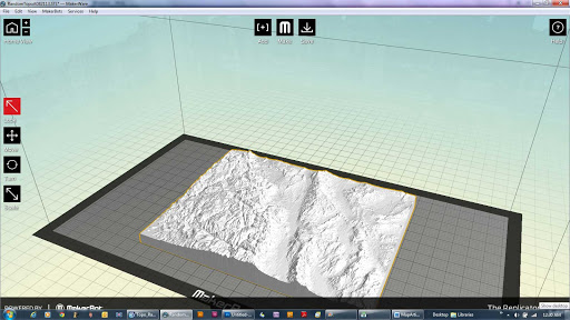
K. Topographic map imported into MakerWare
21. Open MakerWare, MatterControl, or whatever you’re using to drive your printer, and add your STL object, scaling it to fit your print bed comfortably (Image “K”);
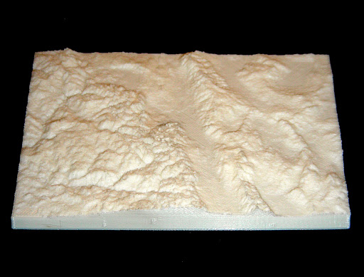
L. The final product - a 3D printed topographic map
22. Print it! This will take a long time to print. My map took almost four hours, but the detail is amazing. This printed object is only about 4.75in x 3.5in (Image “L”).
This may look like a long, difficult process, but it’s actually pretty straightforward if you follow every step to the letter. Believe me: It will be a lot easier for you to go through these steps than it was for me to figure them out.
If you find any mistakes in this article, please point them out, and I’ll do my best to fix them.
Good printing!
Roy Smith
The Smithbot
(Update 2019)
At MatterHackers, we’re always looking for fun and interesting new projects that we can incorporate 3D printing and digital fabrication into. I had remembered seeing this older MatterHackers article by Roy Smith, but it was made clear that this methodology would not allow for the features that make regions recognizable: buildings! With that, I set out to devise and document a process.
Method 1: 3D Map, no Topography
I was able to find a couple of different methods, both free and paid for that worked okay, but the best I could find for my purposes was using a series of different programs to convert data from Google Maps. I wanted to start off with something that was a recognizable landscape or held some significance for MatterHackers, so I’ll use New York City, specifically the area around the Empire State Building and some portion of Downtown Los Angeles.
- Go to opensteetmap.org and find the location that you want to 3D print. This will utilize the data within Google Maps to create 3D models of the area seen in the viewport.
- Click Export to export a .osm file.
- Download and install OSM2World from osm2world.org
- Once installed, open OSM2World and import the map.osm file you exported already. After a minute or so, you should see a 3D model of your city.
- From OSM2World, you can export an Obj file, which some slicers can’t interact with and will need conversion. At this point you wouldn’t want to print it either; this model will need quite a bit of cleanup.
- Open up Netfabb and import the Obj file. You need to delete some of the artifacts from the scenery that couldn’t be translated properly and make the finished mesh printable.
- Using the plane cut sliders, remove the features that extend past the part of your city that you want to keep, like the highways and jagged edges where the map ends.
- Select the city section that you want to keep and open up the repair tool
- Use the surface selection tool to select the land below all the buildings
- Click the “Extrude Surfaces” tool and make sure the “3D-Extrude” tab is selected and “Smooth” and “Thickening” options are selected as well.
- Change “Shift” to 100mm (positive or negative, whichever way extrudes it away from the buildings). Then click apply.
- Now that the land has thickness, click “Run Repair Script” and “Extended Repair.” Netfabb will attempt to merge all the shells into one model, rather than one with many individual parts.
- If you’re lucky, you have one shell and everything looks right, however, odds are your model needs a little more repairing.
- Click the left side of the box next to the Z Cut Plane slider, this will hide anything below the cut plane.
- Look at the model from the bottom and check to see if you can see any blue triangles. This would mean you have buildings that aren’t attached yet, or your building has overhangs on it that need removing.
- Use the “Select Shells” tool to select the mostly finished model, then right-click and hide triangle. This will make it easier to see the other shells that are not connected
- Manually select the bottom surfaces of each of these shells, then extrude them down far enough to stick into the land.
- Do another Extended Repair to merge it with the rest of the model and apply the repair if it all looks good (I opt to not remove the old part in case I need to go back for repair.
- Use the Z plane cut to cut off the bottom of the land and make it completely flat and if you desire, use the extruded surfaces tool again to thicken the base).
That covers Method 1. There’s a lot that goes into it, but in the end, you will have a fairly detailed and really fun model that you can print and modify as you desire.
Method 2: 3D Map with Topography.
The data that is gathered by Google Maps does not include any sort of topographical data. It knows that there are buildings, where they are, where the roads are, how many lanes, but San Francisco’s landscape (a notoriously hilly city) would look exactly the same as Houston (one of the flattest cities in the US). Conveniently, there’s a website that can convert the data from Google Maps, NASA, and the US Geological Survey to create a much more accurate cityscape with included topography.
- Go to CADmapper.com
- Zoom in and out, drag the corners of the selection box, and pan the viewport to change your selection of map you’d like to download. The free version limits you to one square kilometer, but you can select between 1 and 100 square kilometers for $6 to $65.
- Export using SketchUp 2015+, select to include 3D Buildings, and set false height to 20 meters, check the box for Topography, and Road Geometry is up to you (mesh surfaces will allow you to extrude the roads but to make them printable will take a lot more work to make them ready for that).
- Click “Create File” and CadMapper will begin merging all the data it needs to create a workable 3D model.
- When it’s completed, download the finished file and open it up using SketchUp 2015 or newer.
- Under the “Window>Default Tray” Toolbar, make sure “Layers” is selected so you can see and select the layers within the map.
- You can choose to keep all the layers, which will require more cleanup and tuning to get right, or you can keep the main ones to get it printable. Buildings and Topography are the important ones.
- Once you’ve deleted the layers you don’t want, install the STL Import & Export Extension, and export the map as an STL.
- With the exported STL, you can then import this into NetFabb and begin modifying the mesh using the Repair tool.
- Use the surface selection tool to select the land below all the buildings
- Click the “Extrude Surfaces” tool and make sure the “3D-Extrude” tab is selected and “Smooth” and “Thickening” options are selected as well.
- Change “Shift” to 100mm (positive or negative, whichever way extrudes it away from the buildings). Then click apply.
- At this point, if you chose to keep the roads, you’ll need to go through by hand and repair each of them, give them thickness, and make sure there aren’t overlapping triangles; a simple Extended Repair is not going to cut it here.
- Now that the land has thickness, click “Run Repair Script” and “Extended Repair.” Netfabb will attempt to merge all the shells into one model, rather than one with many individual parts.
- If you’re lucky, you have one shell and everything looks right, however odds are your model needs a little more repairing.
- Click the left side of the box next to the Z Cut Plane slider, this will hide anything below the cut plane.
- Look at the model from the bottom and check to see if you can see any blue triangles. This would mean you have buildings that aren’t attached yet, or your building has overhangs on it that need removing.
- Do another Extended Repair to merge it with the rest of the model and apply the repair if it all looks good (I opt to not remove the old part in case I need to go back for repair.
- Use the Z plane cut to cut off the bottom of the land and make it completely flat and if you desire, use the extruded surfaces tool again to thicken the base).
Method 2 is pretty straightforward and can give some interesting depths to your topographical maps and makes for great HexTiles of some of our favorite locations!