
How To Use Support Material: Part 1
Part one of an in-depth look at how to use support material. First up: single extrusion. Learn successful design considerations and how to use support material to create complex prints.
When designing models for 3D printing, the prudent designer will ensure that negative space is minimized and that the positioning of the model on the printer assists in navigating or mitigating that space. However, any designer who has been around the block once or twice knows that there will come a time when the use of supports cannot be avoided. With that in mind, this article will explore some considerations during design to mitigate printing over negative space and to venture more in-depth on the use of supports while printing.
Starting Out
An experienced designer knows that just because an idea or product can be designed does not necessarily mean that it can be made. There are limits in fabrication processes that will dictate what type of designs are possible. For example, machining works well for parts with external surfaces, but surfaces on the interior could pose a problem since the tool needed to make the surface may not be able to access that particular geometry. The same is true during the injection molding process. Sharp angles and “hidden” surfaces are challenging to create.
Those issues are the reason why 3D printing is such a powerful tool. Since the part is built using an additive process, many previously hard to reach geometries may be accessed with little effort. However, there are limitations to 3D printing that the designer needs to keep in mind. These limitations are often printer specific, so knowledge of your printer’s capabilities are of paramount importance.
Printer Limitations
The first consideration is how well your printer deals with overhangs. The rule of thumb is to avoid designing overhangs where the vertical surface angle between the vertical edge of the lower layers and the edge of the overhang is less than 45 degrees. Many printers may be able to navigate angles greater than 45 degrees, but not all printers will be successful. To understand the overhang capabilities of your printer, please refer to the Overhangs section of A Guide to Understanding the Tolerances of Your 3D Printer.
Another consideration is how well your printer is able to bridge. Bridging is defined as the printer's ability to print a solid layer between gaps or negative space in lower layers without the use of supports. Again, bridging is printer dependent, but a good rule of thumb is to keep the bridging distance less than 50mm. Also, for a bridge to be successfully printed, there needs to be a lower contiguous wall or column edge (see Figure 2) between both ends of the base of the bridge. Please refer to the Bridging section of A Guide to Understanding the Tolerances of Your 3D Printer for additional information and to determine your printer’s limitations.
Design Considerations
Now let us look at model design. When dealing with overhangs, it may be possible to achieve the desired form and functionality by designing the part so that the overhang is less than a 45 degree angle from vertical. If the designed part requires an overhang angle greater than 45 degrees, then an arc or chamfer (see Figure 1) may be utilized on the surface next to the negative space to assist in the part’s printability.

Figure 1: 70 Degree (Vertical) Angle With Radius and Chamfer
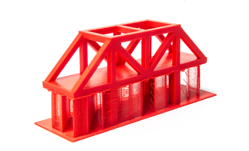
When bridging, make sure that the model has a good base wall or column on each end of the bridge. Also, bridges are direct, straight line shots. When navigating negative space, do not design features or bridges with curves or angles unless you are going to use supports. A printer does not do well when transitioning from straight lines and will leave filament residue along the print path of the feature (see Figure 2).
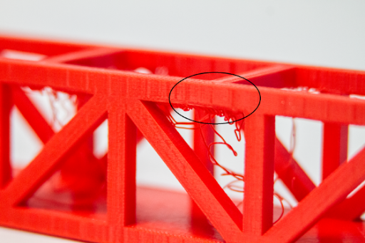
Figure 2: Bridge With No End Column
Finally, a designer may wish to divide or segment the model into individual printed parts to be assembled upon completion. This may be more desirable than using supports, especially if the model is multifaceted with many surface angles. A good overview of segmented designs and printed assemblies may be found at Printing Outside the Box: Exceeding the Build Volume of Your Printer and MatterHackers Lab: Design 3D Printed Assemblies.
Supports
In the prehistoric times of desktop 3D printing (about four years ago), supports were a neglected and overlooked feature of 3D printing practitioners. Supports were often difficult to generate and even more difficult to remove. Now, it is much easier to print with supports and removal is no more complicated than any other standard finishing process. The key is knowing when to use them and how to set them up for printing.
Supports are used when all other methods of mitigating negative space have been exhausted. Creating supports is fairly straight forward when using MatterControl. When adjusting the settings in MatterControl, the “Support Material” section may be located under the “General” tab under “Settings” (see Figure 3). The “Support Material” section reveals a list of options that may be set depending on the type of negative space to be mitigated.
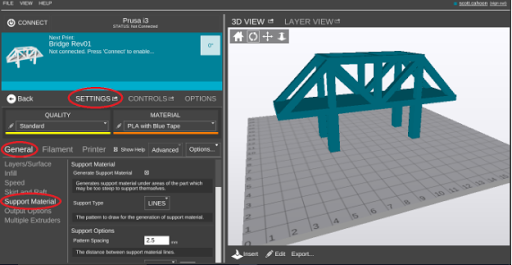
Figure 3: Creating supports in MatterControl
For example, if the model contains many surfaces that fluctuate over a short distance, then decreasing the “Pattern Spacing” will ensure that all surfaces next to negative space will be supported. Another example would be the adjustment of the “Support Percent” depending on the type of feature to be supported. If the model surface area next to the negative space is large, then a higher “Support Percent” may be required to provide a more solid support foundation.
Before delving into specifics, let us look at the basic anatomy of a support configuration. The basic anatomy includes the type of support (“Support Type”), the interface layer (“Interface Layers”), the perimeter (“Create Perimeter”) and an optional raft (“Skirt and Raft”) (see Figure 4). A raft may assist in bed adhesion for the first support layer, but is not essential.
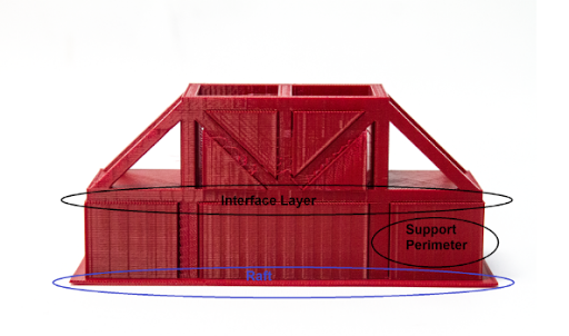
Figure 4: Interface Layer, Support Perimeter, and Raft
The type of support is nothing more than the geometric pattern of the base support, e.g. lines, grid, etc. The interface layer is the solid layer between the top of the supports and the bottom of the part. This layer is extremely helpful when removing supports from the surface of the model since all the support structure is connected to the interface layer and will usually separate from the model in one pull (see Figure 5). The perimeter encompasses the exterior of the support footprint and provides increase stability for the support structure. Finally, a raft may be included for support bed adhesion.
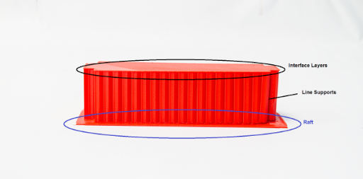
Figure 5: Notice the Smooth Surface of the Interface Layers Upon Removal
Support Specifics
Table 1 lists all the settings that the designer and 3D printing practitioner may adjust to construct the desired supports. For this article seven bridges were printed to highlight the different settings. Use these models as a guide and feel free to experiment with different configurations to obtain the best results.

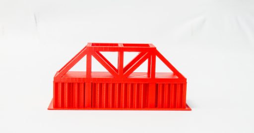
Figure 6: Bridge 1 Front View With 2.5mm Pattern Spacing Line Supports
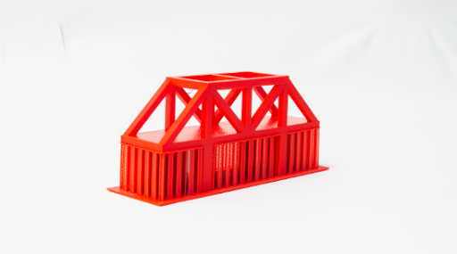
Figure 7: Bridge 1 Angled View
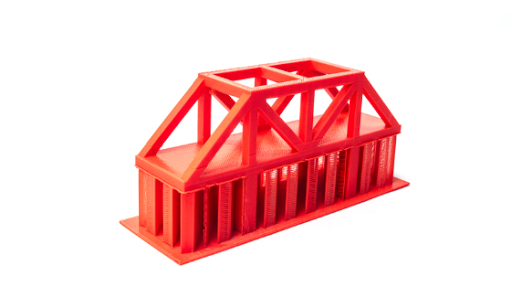
Figure 8: Bridge 2 Angled View With 5mm Pattern Spacing Line Supports
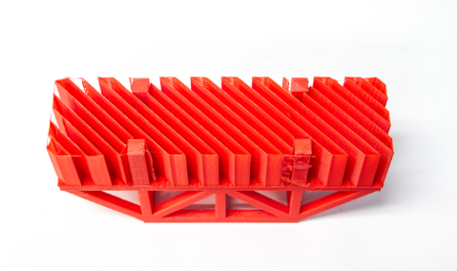
Figure 9: Bridge 2 Bottom View Without Raft
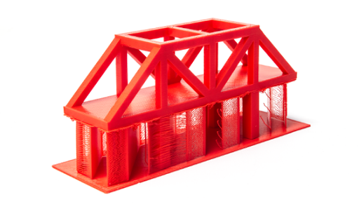
Figure 10: Bridge 3 Angled View With 10mm Pattern Spacing Line Supports
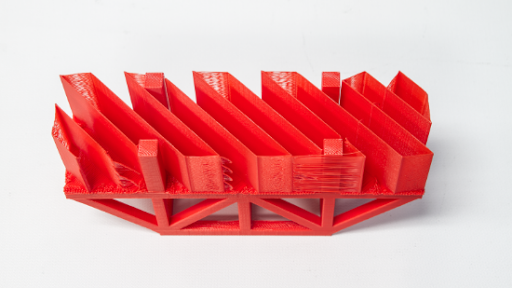
Figure 11: Bridge 3 Bottom View

Figure 12: Bridge 4 Bottom View With 10% Support Percentage and 10mm Pattern Spacing
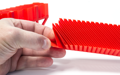
Figure 13: Bridge Bottom View With 50% Support Percentage and 2.5mm Pattern Spacing
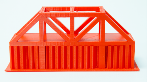
Figure 14: Bridge 5 With No Interface Layers
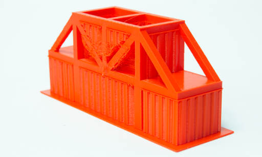
Figure 15: Bridge 6 With Supports Everywhere

Figure 16: Bridge 7 With Supports Everywhere and Support Perimeter
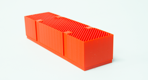
Figure 17: Bottom View of 2.5mm Pattern Spacing of Line Supports With Support Perimeter
From experience, the settings that are frequently adjusted when configuring supports are “Pattern Spacing”, Support Percent”, “X and Y Distance”, “Air Gap” and “Support Everywhere”.
Changes in pattern spacing determines the amount of supports that are used. Usually, the spacing is less if there are numerous surfaces spanning a small distance in the X and Y directions. For flatter model surfaces over negative space, the practitioner may be able use greater pattern spacing distances and achieve the same desired support affects. Just be aware that spacing less than 10mm allows for a decent to good interface layer with a corresponding good part surface finish while spacing greater than 10mm is often problematic.
Adjusting the support percentage determines the density of the support. For large overhangs or surfaces over large negative spaces, a higher support percentage may be advisable. For small overhangs or features, a lower percentage may suffice. Figures 12 and 13 show the flexibility of the supports at 10% and 50% “Support Percent” respectively.
Adjusting the “X and Y Distance” comes into play when placing supports next to parts of a model that abut negative space in the X and Y directions. The default distance is .7mm and may be increased if prominent features next to the negative space need to allow more room for support removal (see Figure 18). This may be advantageous when there are multiple surface changes in the X and Y directions.
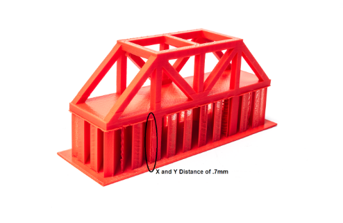
Figure 18: X and Y Distance of 0.7mm
Air gaps are the amount of distance between the interface layer and the bottom of the model surface (see Figure 19). The greater the air gap, the easier it is to remove the support structure. Just be aware that larger air gaps may cause stringing on the bottom of the model. The default air gap setting is .3mm.
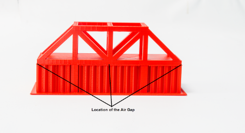
Figure 19: Location of the Air Gap
Finally, “Support Everywhere” means that supports are generated across all negative spaces in the model, regardless of location (see Figure 16). As a result, supports are generated between the bottom of the model and the print bed as well as in areas in the middle of the model where negative space exists.
To Sum It All Up
One final tidbit is to recognize that form and function as it relates to design often determine whether supports are necessary. Usually, if a part is meant to provide a certain function, then often it may be designed where supports are not needed. The designer may be able to add chamfers, radii or segment the part while achieving the desired functionality in the end product. However, when form is the most important consideration, supports often are necessary to complete a successful print. Feel free to experiment as you go and just realize that supports are an aid to your efforts and not a detractor. Above all else, remember to have fun and to enjoy the 3D printing journey.