
Learn How to Punch Pesky Prints Off The Bed with The Automatic Print Ejector
Tyler Anderson, Technical Specialist at MatterHackers, takes you through the process of his creation- The Automatic Print Ejector. This device increases your 3D Printer's autonomy by removing your completed prints off your print bed by punching them with a boxing glove.
The purpose of this device is to remove finished objects from the printer in the most amusing Rube Goldbergish way possible. The original plan was to have a boot swing down and kick the part off the bed, but we decided that a boxing glove would be more hilarious. It is inspired by similar things from old cartoons.
The Automatic Print Ejector is made entirely from printed parts and things we had laying around in the warehouse of MatterHackers. The printer being victimized is an OpenBeam Kossel Pro.

Head over to the Digial Design store to download the files
to create your own AUTOMATIC PRINT EJECTOR
Mechanics
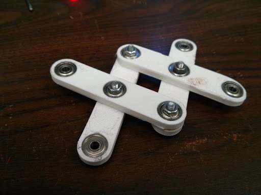
I started off by quickly designing some linkages in Solidworks. The holes fit some little ball bearings we had laying around. Everything is held together with M3 bolts. We had an assortment of different sized bearings, so I had to design parts with a couple different hole sizes. All of the ones posted online are made to fit 9.5mm outer diameter bearings. The holes also include an extra 0.3mm to account for the tolerances of printing.
This was a fun project because most components took less than 30 minutes to print. I could be designing the next thing while the last piece was printing. There was no waiting. In some cases its better to plan everything out at the beginning before you build it, but it can be more fun to just dive in and figure things out as you go along. That's what I did with this project. I ended up with a lot of trashed parts, but who cares.
Everything was printed in PLA since I was not worried about anything getting warm.
Recommended Print settings:
- 0.2 mm Layers
- 2 Perimeters
- 30% Infill
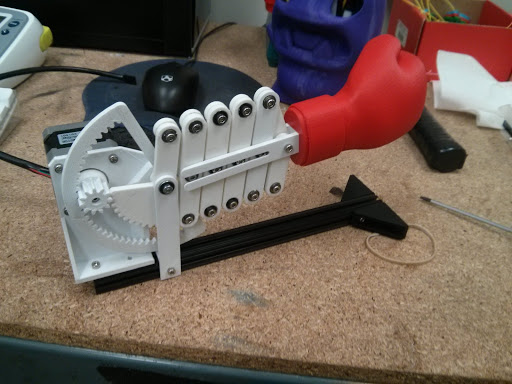
In order to actuate the scissor mechanism, I added a gear to the end of one of the linkages. I also found an old stepper motor to drive it. I could have used a hobby servo, but the stepper is what we had and its got more torque anyways. It also conveniently had a small gear already on the shaft.

This is the bracket I designed to hold the motor and everything. The plan was that the entire device would jut out from the side of the printer, supported by a length of OpenBeam. As you can see, engineering is an iterative process.


At this point it became apparent that only driving one linkage wouldn't work. The entire assembly would just rotate down instead of extending outward. Both of the end linkages need to be forced together or pulled apart in order for the mechanism to work. I added a second gear with inward facing teeth. This way it would be driven in the opposite direction, forcing the linkages together.

Since the gears have different radiuses, there are slightly different gear ratios and one linkage moves slightly farther than the other. This makes the whole thing rotate downward a few degrees when it extends. Oh well. Its good enough.
The boxing glove model was found through googling and I modified it in Blender with a square hole in the bottom to connect it to the arm. This glove turned out to be the most difficult thing to print. Not because it is a complicated shape, but purely because of a series of unfortunate coincidental issues with the printer (some of which involved fire). When it finally did print, the support structure under the fingers failed, so it doesn't have fingertips. I decided I don't care since you won't see that side much anyways.

This is when I ran into the next problem. How do you keep the boxing glove horizontal? I designed a fork shaped thing that would slide over the bolts in the center of the linkages. This makes sure that whatever is attached to the end stays parallel to the mechanism.

Last step was to attach the beam to the bottom and bolt it onto the side of the printer.
I had to design some corner brackets as well in order to connect the beam to the printer's frame. The bed is in the way so I could not use the official OpenBeam T-Brackets. Fortunately I remembered to put some extra nuts in the beams when I was building the printer. Because the thing is mounted perpendicularly on one side, it punches the objects straight into the tower on the opposite side. Eventually I will make some 30 degree / 60 degree corner brackets so it will punch in the right direction.
The 24 cm beam is just barely long enough. The print head narrowly misses the glove while doing the auto-calibration routine and bumps into it a little bit when printing all the way out to the edges.

The finished product.
COMPONENT LIST (What you will need)
- Printed Parts: available from MatterHackers' Design Store
- 1×NEMA 17 Stepper Motor
- 1×Polulu Stepper Motor Driver
- 1×OpenBeam 24 cm Extrusion
- 34×623ZZ Ball Bearings3mm ID, 9.5mm OD
- 14×M3 x 12 Bolts
- 2×M3 x 20 Bolts
- 18×M3 x 8 Bolts
- 30×M3 Nuts
- 20×M3 Washers
Electronics
Wiring was pretty straightforward. I salvaged an old Pololu stepper driver from one of our spare RAMPS boards and used a ribbon cable with female headers to wire it up to the Brainwave. Here is the the wiring diagram from Pololu:
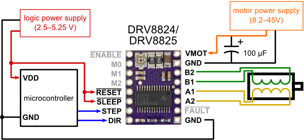
I used the 12V rail from the Brainwave for VMOT as opposed to the 24V rail from the Kossel's PSU. Not sure how much current the 12V line was intended for, but it seems to be doing all right. The STEP, DIR, and EN lines are hooked up to OC1B, OC1C, and OC1A, respectively. I didn't bother with microstepping because I wanted as much torque as possible. A pullup resistor on the EN line might be a good idea but I didn't include it. Here is the pin configuration added to the Brainwave Pro section of pins.h. I had to dig around in Arduino's pins_arduino.h to find the corresponding pin numbers.
#define PUNCH_STEP_PIN 26     // OC1B
#define PUNCH_DIR_PIN 27      // OC1C
#define PUNCH_ENABLE_PIN 25   // OC1A
The motor I found already had a connector on the end of it, but when I plugged it in it didn't want to work. I verified the motor connections using an old trick. If you jump two of the lines together and the motor becomes harder to turn, you know they are connected to the same coil. Rearranged the pins on the connector and everything was good.
Code
The programming is also not complicated. I'm including the interesting parts here but the full thing is available on GitHub. The firmware is based on the OpenBeam branch of Marlin firmware. The changes should not be hard to patch into any other branch of Marlin, though.
I added a new G-Code command (G42) that activates the punching mechanism. It also accepts a feedrate (in Hz) so you can tell it how fast to punch. For example, "G42 F300". If you do not set a speed, it defaults to 50 steps/s. Here is the section from the G-Code parser in Marlin_main.cpp:
    case 42: // G42
      if(code_seen('F')) {
        punch(code_value());
      } else {
        punch(50);
    }
This is the actual punching code in pugilism.cpp.
void punch(float speed)
{
  int delayLength = 1000 / (speed*2);
  SERIAL_ECHOLN("WHAM!");
  // Enable driver
  digitalWrite(PUNCH_ENABLE_PIN, LOW);
  // Set direction
  digitalWrite(PUNCH_DIR_PIN, HIGH);
  // Punch
  // Idea: Ramp up speed
  for (int i=0; i<150; i++) {
    delay(delayLength);
    digitalWrite(PUNCH_STEP_PIN, HIGH);
    delay(delayLength);
    digitalWrite(PUNCH_STEP_PIN, LOW);
  }
  // Reverse direction
  digitalWrite(PUNCH_DIR_PIN, LOW);
  // Retract
  for (int i=0; i<150; i++) {
    delay(10);
    digitalWrite(PUNCH_STEP_PIN, HIGH);
    delay(10);
    digitalWrite(PUNCH_STEP_PIN, LOW);
  }
  // Disable driver
  digitalWrite(PUNCH_ENABLE_PIN, HIGH);
}
Basically it activates the driver, sends 150 pulses to the step pin, then reverses and disables the driver. 150 steps seems to be about the right distance since the stepper motor has 200 steps/revolution and I could tell from moving the linkage by hand that the gear rotates about 3/4 of a turn.
300 steps/s seems to be the ideal speed. It is quick and forceful, but not so fast that it overloads the stepper motor. Sometimes it skips steps while punching but this is fine because it resets its position when it retracts. I had an idea that you could get more power by accelerating instead of punching at a constant velocity. This wouldn't be hard to implement but I haven't done it yet.
Check out the project page at hackaday.io for future updates to this project.
Happy Printing Punching!