
How to 3D Print Clear Filament for Better Transparency
Learn how to produce clearer 3D prints with dry PETG, aligned infill, slow print speeds, tuned flow, controlled cooling, and surface finishing.

Clear filament is useful for light diffusers, LED projects, decorative prints, see-through enclosures, and prototypes that reveal internal features. Just keep expectations realistic: clear filament usually comes off the print bed looking frosted, not glass-like.
That cloudy appearance comes from layer lines, gaps between extrusion paths, and surface texture scattering light. Improving transparency means creating a denser print and smoothing the surfaces light passes through.
This guide uses Bambu Studio and Orca Slicer terminology throughout, since their settings panels are organized a bit differently than other slicers. If a setting name doesn't match what you're used to, check the notes below on where each one actually lives.

Start With Clear PETG
Clear PLA works well when a part mainly needs to transmit light. For parts you want to see through, clear PETG is often a stronger starting point because it offers good transparency and strong layer adhesion.
MatterHackers Clear Translucent MH Build Series PETG Filament is a solid option for testing these techniques. You can also browse the full clear filament collection for additional materials.
Dry the Filament
Moisture is especially noticeable in clear filament. Water inside the material can turn into steam in the hotend, leaving small bubbles that make the print look white or hazy.
Popping sounds, rough extrusion, heavy stringing, and visible bubbles are all signs that the spool may need drying.
Use an active filament dryer and follow the material manufacturer's instructions. The Polymaker PolyDryer lets you dry, store, and print from the same enclosure.
Once the spool is dry, keep it sealed with desiccant to help prevent it from absorbing moisture again.
Choose a Simple Model
Clear parts are easier to dial in when the model has flat or gently curved surfaces, few overhangs and bridges, minimal internal detail, and a consistent cross-section.
The most simple example of this type of model is a cube. Starting with a small test block before printing the final part gives you a quick way to compare settings without wasting much material.
Also consider the viewing direction. A part may look clearer through its top than through its side because the light passes through a different arrangement of layers.
Starting Settings for Clear PETG
Use these as a baseline and adjust for your printer and filament. In Bambu Studio and Orca Slicer, speed, infill, and line width live under Process settings, while cooling lives under Filament settings, more on that split below.
| Setting | Starting Point |
|---|---|
| Nozzle temperature | Middle to upper portion of the recommended range |
| Print speed | 5–50 mm/s, slower is clearer, see “Print Slowly to Keep Air Out” below |
| Layer height | 0.10–0.20 mm, paired with print speed, see below |
| Line width | Standard to start; wider trades some surface detail for fewer air pockets |
| Infill | 100% aligned rectilinear or lines |
| Flow rate | Start at default; test increases of +1–2% or +0.01–0.02 Flow Ratio |
| Part cooling | Off to 30%, set in the Filament settings tab |
| Filament condition | Thoroughly dried |
Change one setting at a time so you can see what actually improves the print.
Use Aligned, Solid Infill
Set the model to 100% infill and choose aligned rectilinear or lines, this is the pattern Bambu Studio and Orca label "aligned rectilinear." Keep the extrusion direction consistent between layers when possible.
Patterns such as grid, cubic, and gyroid leave open spaces and introduce changing line directions. Those features work well for many functional prints, but they scatter too much light for clear parts.
By default, infill runs at a 45 degree angle, but this is adjustable, it's the Infill direction setting in process settings. Try rotating it if you want the internal lines to run parallel or perpendicular to a specific viewing face.
For the top and bottom surfaces, try dropping the shell layer count to 0, or to 1 on the top surface only. Pair a single top shell with a light flow reduction, around 95%, for that layer or two, for a near-ironing effect that smooths the surface slightly without fully closing it off. This is a more subtle, controlled version of the flow tuning described below, applied just to the visible face rather than the whole print.
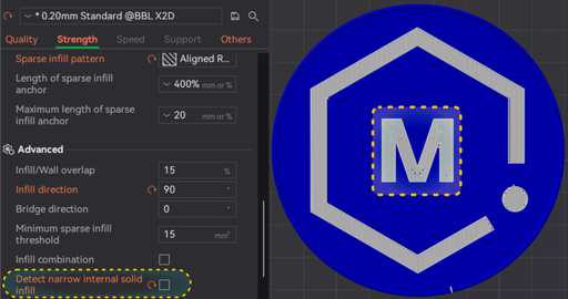
If concentric walls are seen in the print job preview instead of the desired aligned rectilinear pattern, "Detect narrow internal solid infill" may be the culprit. It's meant to clean up thin, awkward infill regions, but on a clear test part it can swap those regions from aligned rectilinear to a concentric pattern instead. That breaks the consistent light path you're trying to build. Turn it off, or at least check a preview, when printing for clarity.
Line width and nozzle size follow the same trade-off as layer height. A wider line width means fewer, thicker extrusion passes to fill the same space, so there are fewer seams between passes for air to hide in. The cost is the same one you'd expect: thicker lines round over fine surface detail and can make the exterior look slightly less crisp. A larger nozzle pushes in the same direction for the same reason, more material per pass, fewer boundaries, less surface refinement. Neither is a must-change setting, but if you're already leaning on taller layers and slower speeds for clarity, a wider line width or a larger nozzle is worth testing as another turn of the same knob.
Print Slowly to Keep Air Out
Print transparency doesn't happen by turning up the heat alone, clarity is the direct result of air having fewer chances to get trapped in it in the first place. Every layer interface and every extrusion path is a place where a small pocket of air can get sealed into the print, and once it's in there, it stays and scatters light.
It helps to picture the nozzle a bit like a squeegee: as it lays molten filament across the layer below, it's pushing air out to wherever there's room for it, along a seam, into a gap, out to the side. Give it more time to do that (slower speed) or fewer passes to do it across (taller layers, wider lines) and it does a more complete job.
That points to two levers that work the same way, in different directions:
Slower speed gives the molten material more time to settle and merge before it solidifies, so bubbles have a better chance to escape or merge out before the layer sets.
Taller layer height means fewer total layer interfaces for a given part height, fewer seams, fewer opportunities to trap air. The trade-off is that if air does get trapped, the pockets can be larger and more visible, since there's more material, and more room, per layer.
In side-by-side testing across 0.1 mm and 0.2 mm layer heights at speeds from 5-200 mm/s, the slowest 0.1 mm samples (around 5 mm/s) came out clearest. But 0.2 mm layers at 50 mm/s came in a close second, nearly matching a 0.1 mm print run at 25 mm/s, likely because the taller layer height was already doing some of the work that slowing down does at 0.1 mm.
Practical takeaway: if you have the time, 0.1 mm layers around 5 mm/s will give you the clearest result. If you want most of that clarity without the long print time, 0.2 mm layers around 50 mm/s is a strong compromise.
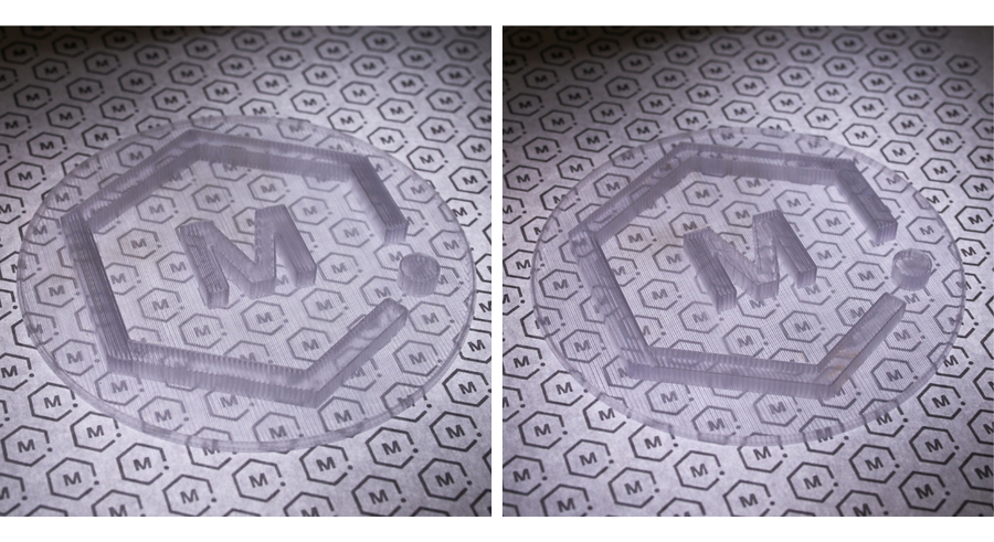
Similar effect, drastically different print time.
There is no need to go slower than necessary once you're in a good range, leaving material in the hotend for too long can cause bubbling or discoloration of its own. Aim for slow, stable extrusion rather than the absolute minimum speed your printer supports.
Adjust Flow Carefully
Even at 100% infill, small gaps may remain between extrusion lines. A slight increase in flow can help fill them.
Start with your calibrated flow rate, then test increases of one percentage point. Stop once the gaps close or the surface begins to look rough.
Too much flow can cause bulging walls, distorted holes, poor dimensions, and material buildup around the nozzle.

Tune Temperature and Cooling
A little extra heat can improve bonding between extrusion lines, but hotter does not always mean clearer.
Start near the middle or upper portion of the filament's recommended range and adjust in 5 degree C increments. Look for fewer internal lines, consistent extrusion, and no bubbles or discoloration.
Low part cooling can also improve bonding and transparency. Begin with little or no cooling on simple geometry. For bridges, holes, and overhangs, try 20-30% fan speed.
If you're used to older slicers that keep cooling as a print-level or platter-level setting, note that Bambu Studio and Orca Slicer put it in the Filament settings tab instead, under Cooling. That's also where you'll turn the fan off entirely for a simple clear test part, rather than in Process settings where you might expect to find it.
Smooth the Surface
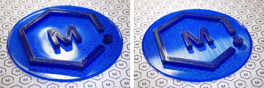
Even a dense print can look cloudy because of its exterior layer lines. Post-processing can make a major difference.
For wet sanding, start around 400 grit and move through progressively finer grits up to 1,500 or 2,000. Once the surface is smooth, use a plastic polishing compound to restore the gloss.
A compatible clear coating can also fill shallow surface grooves. Keep in mind that coatings add thickness and may soften fine details.
Use a Heat Gun Carefully
A heat gun can lightly remelt the outer surface of PETG and smooth some layer lines.
Do not use a torch or open flame. Place the print on a heat-resistant surface, keep the heat gun moving, and test on a scrap part first.
Too much heat can quickly warp the print, soften details, create bubbles, or leave uneven glossy patches. This method is fast, but sanding gives you much greater control.
Quick Troubleshooting
| Problem | What to Try |
|---|---|
| Print looks white or hazy | Dry the filament and check for under-extrusion |
| Small bubbles appear | Dry the spool, slow down, or increase layer height |
| Extrusion lines are obvious | Slow down or slightly increase temperature or flow |
| Walls look swollen | Reduce the flow rate |
| Overhangs look distorted | Add a small amount of cooling |
| Interior looks clear but the surface is frosted | Sand, polish, coat, or carefully use a heat gun |
| Thin sections don't match the rest of the infill pattern | Check “Detect narrow internal solid infill,” it may be switching those areas to concentric |
Final Tips
The clearest FDM prints usually combine dry PETG, simple geometry, aligned solid infill, slow printing at a layer height that limits air entrapment, carefully tuned flow, cooling turned down or off in the Filament settings tab, and surface finishing.
Start with a small test piece and adjust one setting at a time. Once you find a combination that works, save it as a dedicated clear-printing profile.
Browse clear 3D printer filament at MatterHackers to find a material for your next transparent or translucent print.