
How To: Bring Video Game Characters to Life
3D printing has been a game changer in the cosplay world. Learn techniques from our resident cosplayer to turn digital models into physical costumes.
In the past, creating an object based on a video game was difficult, time intensive, and generally accomplished by hand. My background in 3D printing comes from cosplay, and the most common question I am asked is "how do you make your costumes?"
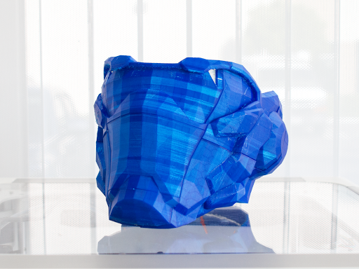
3D Printed Soldier 76 from Overwatch
I used to to explain the lengthy and complicated process of using a Japanese papercraft program, Pepakura, to assemble a paper model, and coat it in noxious polyester resin and fiberglass to strengthen it. Now, the answer is much more concise: “I 3D printed it,” and the process is immediately understood.
With the momentum of 3D printing, the process of creating something for cosplay is transitioning from physical crafting to digital fabrication.
Thanks to many generous makers and groups, it is very easy to find 3D models of objects from video games. Sometimes these models are created by a maker looking at pictures from the video game as a reference for their sculpt, and these are usually able to be printed without issue. Other times, models will be extracted or “ripped” from the coding of the video game, and these almost always come with problems.
In order to save processing power of computers or consoles, developers will create helmets or guns or vehicles in games by mashing different pieces together. Rather than make two parts that perfectly fit together, like a phone case on a phone, they would just make the two pieces morph into each other. When parts are morphed together, this can create holes in the model, preventing it from being printed correctly. This means they are not "watertight", which is the key to any successful 3D print.
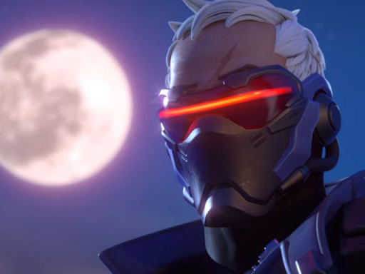
Soldier 76 from Overwatch
The example I am using is Soldier 76’s mask from Blizzard’s new game Overwatch. The model was found by Replica Prop Forum member, sturds. When you “Select All” in Sketchup, it will select all the faces of that model. As you can see here, the visor isn’t selected and yet it is touching the rest of the mask (Figure 1). This is an example of this “morphing” and it is especially important to notice the corners of the triangles don’t touch (Figure 2).
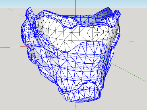
Figure 1
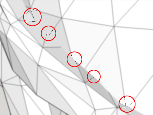
Figure 2
To fix these issues, you’ll need three programs, all of which are free:
- Google Sketchup
- Autodesk Meshmixer
- Autodesk netFabb
Step 1. Set up Sketchup
Using the Extension Warehouse (Figure 3), find “Sketchup STL” and install it. This will allow you to export and import STLs with Google Sketchup. (Figure 4)
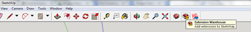
Figure 3
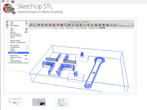
Figure 4
Step 2. Draw it out: Connecting the separate pieces.
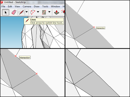
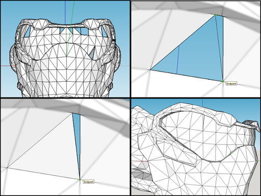
Google Sketchup’s “Lines” tool has the handy feature of letting you know when there is an intersection between two lines. This will be used to redefine the borders of the visor to connect it to the rest of the mask.
-
Select the “Lines” tool. (Figure 5)
-
Hover over what looks like the endpoint of a line (zoom in as close as you need to).
-
When you see a red X and it says “Intersection,” click. (Figure 6).
-
Move the cursor to the next endpoint until another red X appears, click. (Figure 7)
-
You’ve just connected the two parts together, but now this needs to be repeated around the entire edge of the part.
-
Repeat until loop has been made. (Figure 8)
Note: Sometimes, for reasons I don’t know, Sketchup will not allow you to click on the intersection. Sometimes I come back to it later and see if fixing the rest helps that point, and if it doesn’t, I create a line as close to where it should be as I can.
Top row(from left to right): Figure 5 and 6. Bottom row: Figure 7 and 8
Step 3. Filling it in: Patching holes in the model.
Occasionally, there will be holes in a model. Either the original had it or in the process of connecting the two parts, a hole was created. This is just as easy as connecting the parts
- Click on the last endpoint where the two parts are connected.
- Shifting the camera around, try to figure out where the part should have continued, and click on the line to create the face.
- If a face isn’t created, connect points diagonally as necessary to create triangles.
- Repeat until the other side is reached, where the two parts meet again.
Step 4. Clean up inside
On the inside, there are now sections of the model that aren’t necessary. Essentially, this step is about trimming away what has separated by step 2.
-
Find the edge where the two faces meet, the one you want to keep (in this case the visor) and the one you don’t (the trim around the visor). (Figure 10)
-
Using the “Select” tool, highlight the edge on the face you don’t want. (Figure 11)
-
Press the delete key.
-
Two faces should have vanished. The edge that you deleted is what defined how those two faces were oriented, without it they can’t exist. (Figure 12)
-
Repeat this all along the edge, deleting all the lines that are behind where you marked in Step 2.
-
When you are done, you should have 2 outlines showing where the visor and trim extended out to. Double clicking on them will highlight them. (Figure 13)
Press the delete key and they should be gone. (Figure 14)
Top row(from left to right): Figure 10 and 11, Bottom row Figure 12 and 13
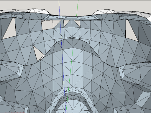
Figure 14
Step 5. Clean up your mess: Patching new holes
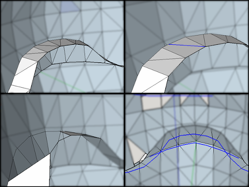
As you saw what happened when we deleted the line defining the two faces, the same has happened to some of the faces we wanted to keep. Here’s how we bring those back: (Figure 15)
-
Using the “Line” tool, select the endpoint that doesn’t have a triangle attached to it.
-
Click on an endpoint opposite from it. (Figure 16)
-
This creates one triangle to cover that hole. (Figure 17)
-
Repeat as necessary until all holes are covered (Figure 18)
Note: Sometimes it won’t be clear which opposite endpoint is the right one to pick. Try each one until you see the right contour to the model. E.g connecting A to B creates a really jagged edge where it should be smooth, but A to C is a nice smooth surface.
Top row(from left to right): Figure 15 and 16, Bottom row Figure 17 and 18
Step 6. Hose it off (Optional)
Soldier 76’s mask in Overwatch has a hose on either side of it. Personally, I would rather remove this from the model and use some real hose for this rather than attempt to clean it up with sanding and painting it. If you’d prefer to leave something like that on, that’s totally fine too.
-
Just as we did with the faces behind the visor, select each edge that belongs to the hose, and delete it. Use your judgement to find which faces you don’t want to keep; it does take a little experience to gauge where one feature starts and the other ends. (Figure 19, 20, 21)
-
Export your finished model as an STL
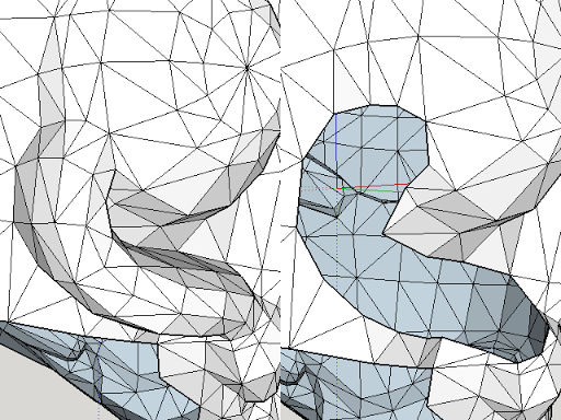
Figure 19 left, Figure 20 right
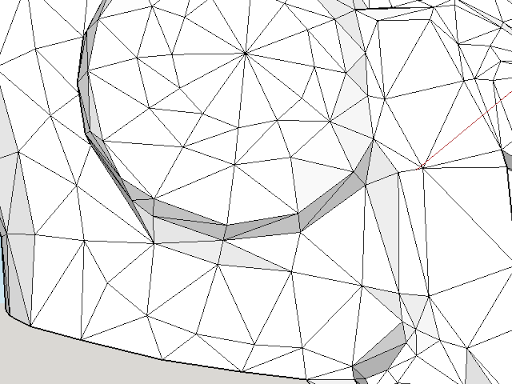
Figure 21
Step 7. Large scale production: Sizing the mask to fit you.
Models from video games don’t usually have units. You may download something and find it’s the size of a house or it’s the size of a dime. The size of any model needs to be adjusted to be sure it fits right. In this case, for a mask, head size is the important measurement.
There are several different ways to do this, this one looks the silliest.
- Take a ruler and lay it on a table.
- Stand a thick book on top of the ruler so it is at zero.
- Take another book and stand it up at the other end of the ruler
- Put your head between the two books, keeping the one at zero stationary, move the other book closer until each book is just barely touching your ears.
- The distance on the ruler is your head size.
- This is the minimum Width of the mask.
- Repeat for Length and Height to ensure proper fit.
- Note: You may need to add 1” to the measurement to allow for padding (½” on each side). Looking at reference material for Soldier 76 makes this a tough call, as the mask looks more like it’s a close fit like Iron Man rather than like a helmet. In this case you will need to make a judgement call: make it fit to your head and deal with the discomfort of not being able to move your face much but have it look like references, or do you add room to pad it, be comfortable, and be slightly too large of a mask. Whatever your choice:
- Open Autodesk MeshMixer and import your STL
- Click Edit, Transform. (Figure 22)
- Down in scale, change one value until they are all larger than the three values you found. (Figure 23)
-
- If one value is smaller than the one you found for your head size, play around with the numbers until one is the same and the other two are slightly larger. You should only change one number to keep the proportions of the model the same.
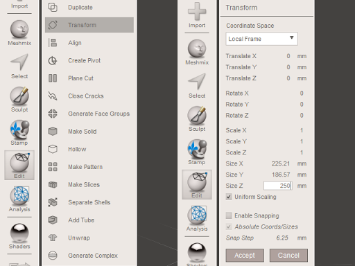
Figure 22 left, Figure 23 right
Step 8. Mix it up: Using Autodesk Meshmixer to thicken your model.
At this point, the model we have cleaned up is essentially paper thin, much too thin for your printer to be able to do anything with. Using the features within Autodesk Meshmixer, we can thicken the model.
-
Select the entire helmet (Ctrl+A). (Figure 24)
-
Click Edit, Offset (Figure 25)
-
Adjust the Offset Distance until you don’t see the black and white stripes on the inside (In my case about -3.5).
-
Adjust Accuracy and Resolution to 100%
-
Check the box for “Connected,” this makes the offset part of the model rather than a separate one. (Figure 26)
-
Export as an STL.
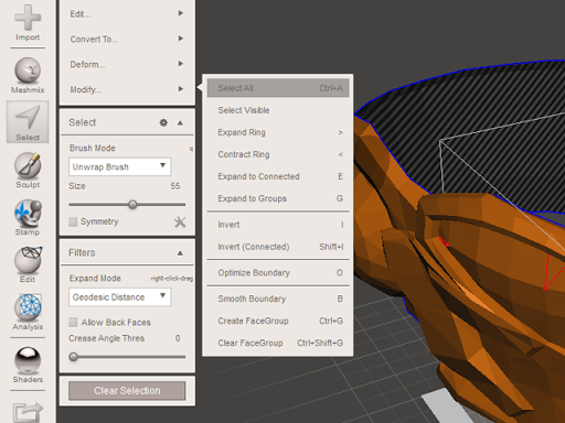
Figure 24
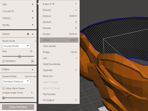
Figure 25
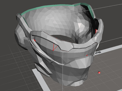
Figure 26
Step 9. Cram it in: Fitting a full size mask on your print bed using Autodesk netFabb Basic
Most printers can’t print larger than 180mm squared, or so. We’ll need to cut the part into separate pieces. For something like this, I prefer not to use dovetail cuts or mechanically join them, as I finish them afterwards with paint and putty anyways. If you’d like to use something like that, check out Scott’s article exceeding build volume.
- Import the STL you created with Meshmixer into netFabb Basic
- Move the model until it roughly has one corner at the origin. (Figure 27)
- Using one slider at a time, adjust the plane that will cut the model into sections.
- I chose to split it in spots that would be easy to sand or glue together. So I adjust the Y slider until it was roughly centered on the ear mounds. (Figure 28)
- Press execute cut.
- Select “Cut all parts.”
- Press Cut. (Figure 29)
- The model is now sectioned in two.
- Repeat until the model is split into enough pieces to fit on your printer. I split it again in front of the cheek details on the Y plane, below the peak of the nose in the Z plane. (Figure 30)
- Note: If you don’t want to slice through all parts within the window, select one part (it will turn green) and change “Cut all Parts” to “Cut only Selected Parts” (Figure 31).
- Right click on each part you have cut out.
- Select Export. (Figure 32)
- Name and save the part as STL. (Figure 33)
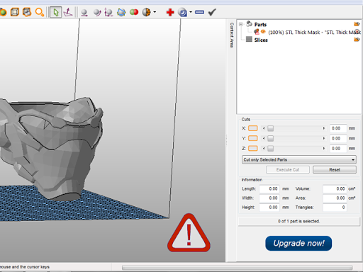
Figure 27
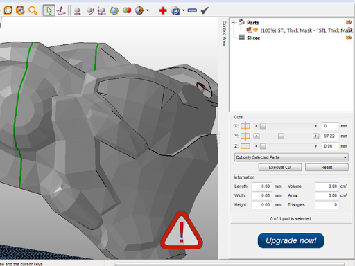
Figure 28
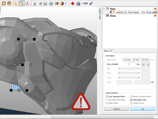
Figure 29
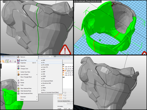
Top row: Figure 30 and 31, Bottom row Figure 32 and 33
Step 10. Some assembly required: putting it all together.
Break out your Crafty Pen and use it like you're making welds. Use some painter's tape to hold two pieces flush, then extrude a thick line onto the back of the seam. With a little practice, it should take only a minute or two to weld two pieces together.
And that's it! You now have a full scale, personally sized, Soldier 76 mask. Stay tuned for future articles on how to even out the seams, clean up print lines or stringing scars, and smooth out the rough shape of the original 3D model.