
Living Hinge: Design Guidelines and Material Selection
Bring your prints to life by adding an additional degree of motion to your designs - living hinges are the foundation of expanded mechanical solutions.
A living hinge is a connected portion of a whole part that is thin and flexible enough to allow movement between two otherwise rigid sections of the same part. These sections are designed in such a fashion that all three sections (two rigid sections and one hinge) are fabricated in one single form. The hinge section is designed to allow rotational movement (180 degrees or greater) between the sections and in a configuration where it will not fail during the life of the part. This type of hinge is common among injection molded plastic parts but is slowly being incorporated into Fused Filament Fabrication (FFF) 3D printing solutions.
In traditional 3D printing applications, the source material of ABS or PLA were not good choices for printing living hinges. ABS and PLA do not exhibit the necessary properties for function and sustainability. It is only within the last three to four years that materials have been developed to assist in the design of living hinges. These materials include Nylon, TPE (e.g. NinjaFlex), TPU, Soft PLA, Bendlay and even the injection molded staple material Polypropylene. The use of these materials has expanded the options for living hinges in a variety of solutions where injection molded hinges relied exclusively on Polyethylene and Polypropylene.
Ideal Material Properties in Living Hinges
The two most common properties to measure quality in plastics are tensile strength and strain. Tensile strength is defined as the amount of stress that a material can withstand before failure. In other words, it is the amount of force (compression, tension, shear, bending and torsion) necessary to break the part. Strain is the ability of a material to accommodate deformation before failure. This is commonly measured by the part’s deformation in comparison to a reference length. These are two properties where ABS and PLA fail to make the grade (see Figures 1 and 2).
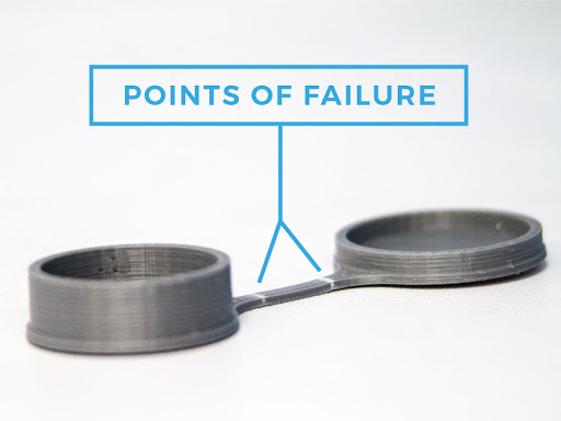
Figure 1: PLA Butterfly Hinge
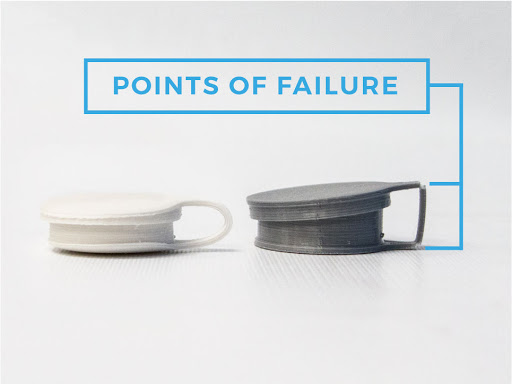
Figure 2: Polypropylene and PLA Butterfly Hinges
Types of Living Hinge Designs
There are four types of living hinges common to injection molded parts: flat (see Figure 3), double, butterfly (see Figure 10) and bi-stable. For 3D printed parts, the most common solutions are the flat and butterfly hinges. Double and bi-stable hinges are often difficult to print due to the negative space surrounding the hinged sections. Another hinge solution takes its origin from the woodworking space: the kerf bend (see Figure 4). A kerf bend is a patterned cut, traditionally the width of a saw blade, that is useful in large radius bends. Kerf bends have also demonstrated utility in 3D printing for those that are looking for creatively designed, patterned radii in printed parts. Patterns run the gamut from triangles and diamonds to beehives, crosses and waves.
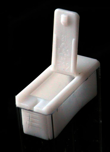
Figure 3: Example of a Flat Hinge (Tic Tac Box Lid)
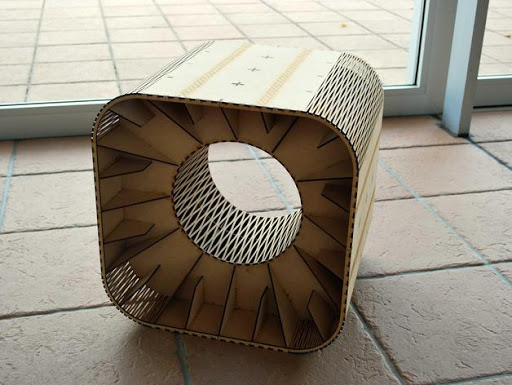
Figure 4: Example of a Kerf Bend (Hisashi Imai)
The design of a living hinge takes into consideration the ability of the material to withstand strain and the material’s tensile strength. With injection molding, the main design focus is on the hinge’s thickness, recessed flat sections and radii. In 3D printing, an additional design element are the radial connections. In other words, radial connections between the hinge and rigid sections as well as the radii around the bend are of utmost importance. If these elements are properly addressed, the resulting part will be an effective utilitarian component of your product.
Figure 5 shows the typical design of a flat hinge for injection molding. Notice the recessed portion on the top of the hinge along with the radii essential to keep the hinge structure sound upon continual usage.
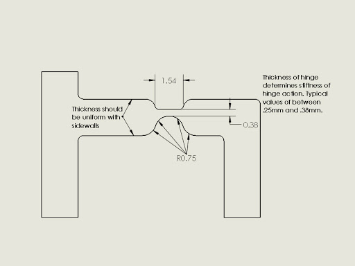
Figure 5: Flat Living Hinge Design for Injection Molding
Flat living hinge design for FFF materials and processes follows the same design principles with the exception of hinge, recessed and radial thicknesses and lengths. Since average FFF layer heights range from 200 - 250 microns, hinge thicknesses of 250 - 380 microns used in injection molding solutions most likely will not work with FFF solutions. As a result, the hinge design will need to be altered to accommodate FFF.
Figure 6 shows the typical design of a flat hinge for FFF. Notice that the hinge and radial lengths and thicknesses have increased. This results in a stiffer motion due to the increased hinge thickness. Figures 7 and 8 show the resulting 3D print of the design in nylon.
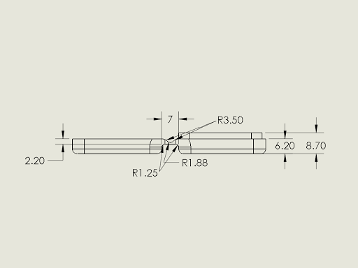
Figure 6: Flat Hinge Design for FFF 3D Printing
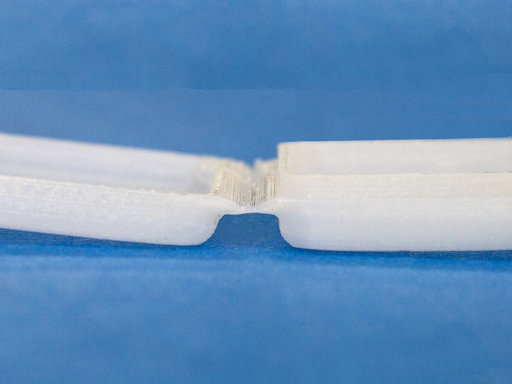
Figure 7: Example of Flat Hinge in Nylon (Open)
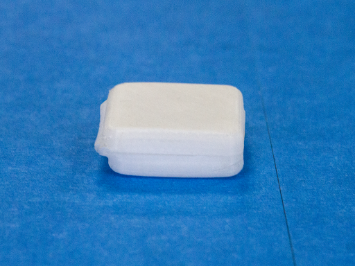
Figure 8: Example of Flat Hinge in Nylon (Closed)
Butterfly living hinge design for FFF materials and processes follows the same design principles as injection molding with the exception of hinge thickness and length. The hinge width and radii may be kept the same. Also notice how the hinge may be printed without having to account for any negative spaces in the design. Most likely the butterfly hinge is the easiest hinge to print in the FFF process. Figure 9 shows a typical design of a butterfly hinge. Note the hinge length, thickness and radial components. Figures 10 and 11 show the resulting 3D print of the design in nylon.
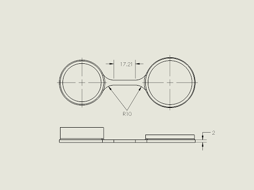
Figure 9: Butterfly Hinge Design for FFF 3D Printing
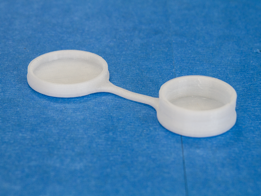
Figure 10: Example of Butterfly Hinge in Nylon (Open)
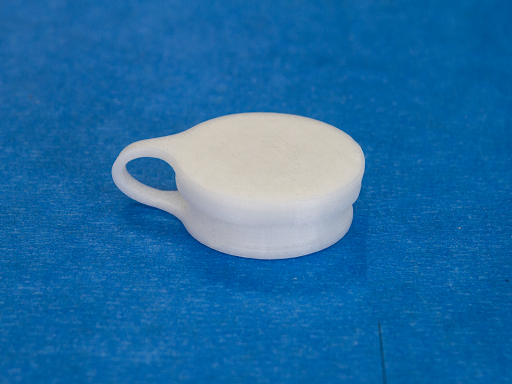
Figure 11: Example of Butterfly Hinge in Nylon (Closed)
Kerf bends add an interesting dynamic to a hinge portfolio where the bends are as much aesthetic as functional. Kerf bends not only provide rotational movement (see Figure 12), but are also used in oscillating configurations (see Figure 13). The basic design (see Figure ) consists of a bend length of at least 25% of the entire part. The width of the bend is the same as the width of the part. Notice how the side edge (see Figure 14) contains negative or open portions of the design pattern. This allows for additional freedom in the joint when rotating or oscillating the part. Your imagination is the only limit when designing and utilizing the kerf bend solution. Just follow the basic design guidelines in Figure 15 and you will be on your way to creating movable and aesthetically pleasing designs and parts.
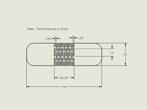
Figure 15: Kerf Bend Design for FFF 3D Printing
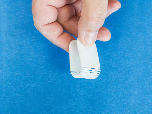
Figure 12: Example of Kerf Bend in Nylon (Full Rotation)
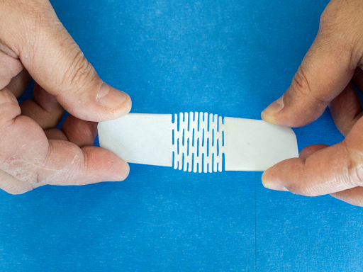
Figure 13: Example of Kerf Bend in Nylon (Oscillating)
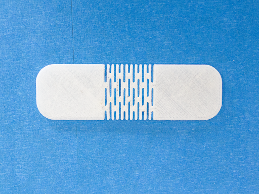
Figure 14: Example of Kerf Bend Design in Nylon (Open)
As a final note, be careful of the types of materials that you use in your mechanical hinge solution. If you are fabricating a critical part, stick with the materials that have proven to have the tensile strength and are able to withstand strain over the life of the part. These materials include nylon, TPE and polypropylene. If the part is not critical in the overall use and functionality of your product, feel free to experiment with TPU, soft PLA and Bendlay. Also, keep plenty of radii in your design and try to avoid sharp angles unless it is absolutely necessary. Remember that fabricating living hinges in the FFF process has opened the door to many more design and part possibilities than traditional injection molding processes. Seize the opportunity to explore how living hinges may assist you in bringing your complete product to life.