
How to Use Tinkercad - Free 3D Modeling Software
Learn how to use Tinkercad, the reliable and user-friendly 3D modeling software. Perfect for educators, students, and makers alike, Tinkercad will help take the ideas you have to printable form as smoothly as possible.
Overview:
Educators and students will learn how to use the free, simple, online 3D design and 3D printing app, TinkerCAD. It’s a free, easy to use, 3D modeling program that doesn’t require any prior design experience, but can still be used to create helpful tactile and visual aides for teaching or can even be used by the students to develop their understanding of a subject, like designing a coin that the Ancient Egyptians might have used.
To see Tinkercad in action and learn the basics of using the platform to design, check out the video form of this article as well:
Objectives:
Students should be able to navigate and understand how Tinkercad works for basic modeling, and be able to create their first model for 3D printing.
Subjects:
This lesson needs to be taught before any other lessons in our curriculum, (unless you or your students already use another 3D design software) as they utilize Tinkercad. After this lesson, Tinkercad can be applied to any subject as a learning tool, from creating fraction models for math, the states of matter for science, or Native American home styles for social science, Tinkercad has a lot of versatility.
 TinkerCAD, the free and easy introductory modeling program
Duration of Lesson for How To Use Tinkercad:
Having students follow the instructions in stages with you will take about 1 hour to fully teach the lesson.
Preparation
Students need to know:
- How to navigate on computer and follow instruction.
Lesson Plan and Activity
Step 1: If the student already has a Tinkercad account, have them click the "Sign In" button in the top right corner and proceed to Step 5
Step 2: If they don't have an account, have them click "Sign Up" next to the "Sign In" button.
Step 3: Have the student fill out the webform by inputting the country they live in and their birthday. This is to make sure that parents or teachers of any students under the age of 13 are informed of the sign-up request. Then have them decide on a username and password. Make sure to have them write it down somewhere so they don't forget it.
Step 4: If the student is under 13, have them put in the instructor's email where it says "Your parent's email." When they are all filled in, click "Create Account"
Step 5: Have them click on the Tinkercad logo on the top left; this should bring them to their dashboard. In order to make their own models, click "Get approved," and check the email registered to the account to approve it.
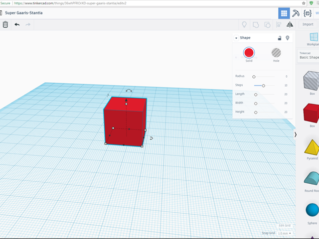
Step 6: At the homepage (Tinkercad.com after logging in) they should click "Create new design" to begin working on their first model and learn the tools within the program.
Step 7: Circled here are the main features we will be focusing on:
- The title for each document is automatically generated, but can be changed at any time by clicking on the title.
- "Workplane" is the surface that students will be working on. It is Z=0 in the Cartesian Coordinate System. Think of it as the base that a clay sculpture will be built from.
- These are tools to create new components and shape them as you want.
- "Workplane" is used to create new planes to build off of, like if you want to add objects directly off of the side of a piece, or if you wanted to make an upside-down "L."
- "Ruler" is used to measure how the length, width, and height of a selected object, as well as how far away it is from a specific point. You can also use this to change the scale, or how large, the model is.

The main tools of Tinkercad
Step 8: Navigating around the workspace using the buttons on the left side of the screen.
- The cube is used to view the workspace straight on from specific angles, selected by clicking either faces, edges, or vertices.
- "Home View" will take you to an angle that is halfway between a top view and a front view.
- "Fit view to selection" will zoom in or out to the selected objects.
- "Zoom In" zooms in and "Zoom Out" zooms out.
- "Switch to orthographic view" is a toggle. Clicking it will change the workspace back and forth from orthographic to perspective. Orthographic gives a view straight view at an object, whereas Perspective will skew the object so it has some depth. "Orthographic" is better utilized if you are trying to get an accurate measure of your objects, and "Perspective" is better for viewing what your finished print will look like.
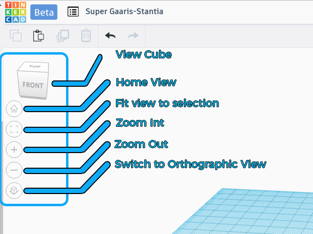
Tools to navigate the workspace
Step 11: To create some basic objects, there is a dropdown menu on the right that says "Tinkercad > Basic Shapes".
Step 12: Using the left mouse button, click on the "Box" and move the cursor over to the workplace and click again to place the box there.
Step 13: By placing the box, several toggles will be created around the box that can change it's shape.
- The white squares are for dragging that corner, which will modify the length and width of the box.
- The black squares will pull only that edge modifying length or width one at a time.
- The one lone white square in the center of the top face of the cube that changes the height of the box.
- The various bent arrows rotate the box around the three axes. If you click and drag inside the circle that pops up around the box, the degrees lock to multiple of 22.5 degrees, but if you drag outside the circle, you have free range of any whole number angle.
- The straight arrow on top of the box is used to pull or push the box away from the work plane. This is helpful if you’re trying to stack parts on top of each other, like a cone on top of a cylinder to be the peak of a castle. Just click and drag to the height you want.
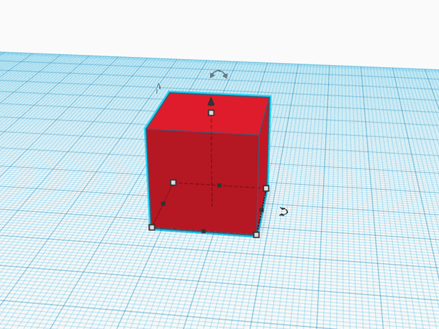
The modification tools on an object
Step 14: Additionally, there is a pop-up menu that offers several more options that affect your object more specifically, but some of these options disappear depending on the object selected. For a box, there is:
- "Solid" means the object is solid, if printed it is a tangible section.
- "Hole" is the opposite of solid, and where it intersects with another objects it will be taken away from it, even if it's off to the side and not a hole through the center.
- "Radius" adds a fillet, or rounding over of the edges of the box or object; he larger the number, the deeper the rounding.
- "Steps" affect how smooth the "Radius" is; the larger the number, the more gradual the curve.
- For a box, "Length," "Width," and "Height" are displayed and can be precisely modified, but for a triangle, only "Sides" is displayed. Each object has its own set of options.
- In the top left is a little lock which will "Lock Editing"; once that is clicked there is no moving the object or changing anything about it until the lock is clicked again.
- The little lightbulb will hide the object completely.
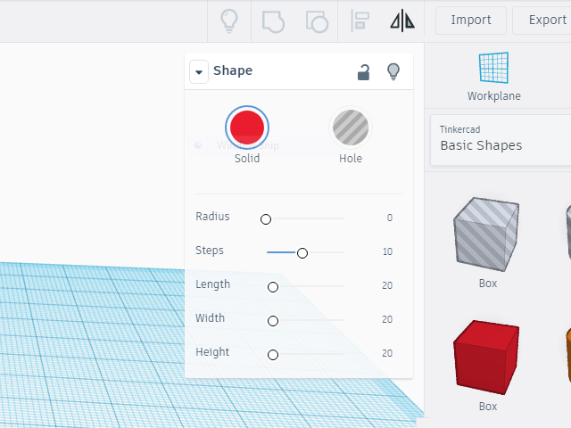
The object modification panel
Step 15: There are tools on the top left for some actions your students' are probably most familiar left.
- "Copy" will take all the objects you have selected and copy them to your clipboard.
- "Paste" will take the objects in your clipboard, and place them slightly to the right from where they were originally copied, or slightly to the right of the object selected.
- "Duplicate" will copy and paste the selected object in the same object.
- "Delete" will remove the selected object or objects from the workspace.
- "Undo" will work exactly like any other program, and undo the last action you did.
- "Redo" will also work exactly like other programs and will take you forward one action.
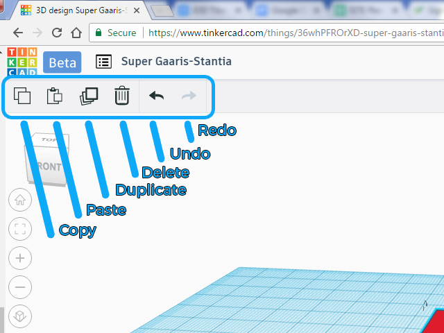
These tools are located in the top left
Step 16: There are a couple more tools that are incredibly useful to making objects more complex than cylinders and boxes, which can be found in the top right.
- "Show All" will unhide any objects that have previously been hidden.
- "Group" will take all objects that are selected and make them one. Once objects are grouped, the modification menu will disappear, except for making them "Solid" or a "Hole."
- Note: Grouping a "Solid" object and a "Hole" will subtract the "Hole" from the "Solid."
- "Ungroup" will simply do the reverse, ungrouping sets of objects, one grouping at a time, so the entire set won't be undone all at once.
- "Align" will align two edges with each other, or two faces, etc.
- "Flip" will pop up arrows along each axis, simply click on one arrow and it'll flip the model in that direction.
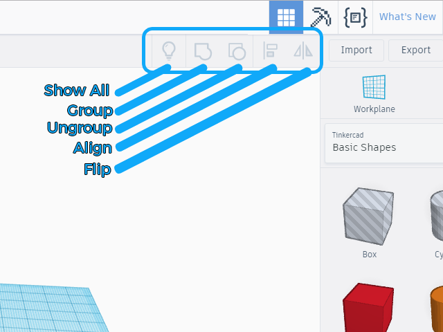
These tools are located in the top right
Step 17: Once the students have played with all the various tools and have a feel for how Tinkercad works, it's time to learn how to export a model for 3D printing. 3D printers use a specific file format, like Microsoft Word uses ".doc" 3D printing programs use ".stl." After export, students will be able to import their .stl into MatterControl.
- Click "Export" in the top right corner.
- Pick either "Everything in the design" to export all the shapes as one file, whether or not they are connected to each other or pick "Selected shapes" to export only the shape that is selected on the workplane.
- Pick either ".STL" or ".OBJ." STL is for 3D printing, OBJ is for modeling in other programs.
- ".SVG" is another file format if you've created something flat and want to use that as a template for a laser cutter.
This concludes the first foray into 3D model design using Tinkercad. Students should continue to experiment with their models by adding several different shapes on to the Workplane and seeing if new shapes may be constructed by overlapping and/or combining the basic shapes. This is the modern version of build and play and students should be encouraged to explore the process in more depth.
Rubric and Assessment
By the end of the project students should have an introductory understanding of how to use Tinkercad. For assessment purposes, students should create any object that utilizes a variety of Tinkercad's functions, like combining two shapes, modifying their dimensions, adding holes, and using the radius tool in the popup.
Tips & Tricks for Printing
- Some students may instantly understand how Tinkercad works, others may need some more hands on help. For most, 3D modeling is a completely new subject they are going to have to learn to navigate. Before moving onto the next set of steps, make sure each student has followed along with those steps.
- Print out the students' models when everyone is finished, so they have tactile feedback for all the work they did.