
A Guide to Understanding the Tolerances of Your 3D Printer
Understanding your 3D printer’s limitations and how these may influence the design and production of 3D printed parts will guide you along the path of producing the highest quality products.
Most users of Fused Filament Fabrication (FFF) 3D printing technology understand that the resolution on finished prints / parts is typically 100 microns or greater with some manufacturers claiming printer resolution of 50 microns.
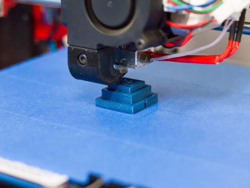
Figure 1: Printing the Dimension Accuracy Model
Resolution is only one criteria that experienced users apply to determine the quality and value of a 3D printer. In an annual competition, Make Magazine convenes a Digital Fabrication Shootout to assess the quality of machines at different price points. Make’s testing criteria is useful for any owner or user of a 3D printer to determine the tolerances and quality of their equipment.
The criteria and corresponding Test Print Models run the gamut from precision / accuracy and finish to machine capabilities. There are nine major factors to consider during the testing of your 3D printer. These factors are listed below and expanded upon with causal details and methods of mitigation in order to produce the highest quality models and parts.
Dimensional Accuracy
Dimensional accuracy is nothing more than demonstrating that your finished print / part possesses the same dimensions of the original part or design. This is often problematic when the base or bottom of a part is next to the bed. Heat and curing may cause warping and often the initial base layer of a print is programmed with extrusion rates in excess of 100% to ensure that the part adheres to the bed (See Figures 1 and 2). This results in a wider initial layer and with resulting dimensions greater than designed. Many users attempt to mitigate this concern by utilizing a raft base before printing the first layer of the actual part.
One should also consider the implications of infill on the completed part. With 100% infill, the amount of material when cured may overlap or extend the finished part beyond the desired dimensions. There is also an opportunity for warping during the curing process. From experience, a MatterControl infill setting at 85% works best for a quality maximum infill.
Finally, be aware that the layer height set for the z-axis has a direct correlation to dimensional accuracy in the z-direction. Often times, the best method to ensure dimensional accuracy is to print at a layer height of 100 microns and to set the perimeter speeds between 15 - 30 mm/s.
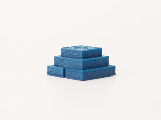
Figure 2: Example of Over Extrusion and Warping
Horizontal Surface Finish
Next to warping and stringing, surface finish is the characteristic most noticed by the end user. Surface finish is often material specific with PLA having a notoriously poor surface finish. One method to improve the horizontal surface finish is to lower the top / bottom layer extrusion speeds to within 15 - 30 mm/s. It may also help to increase the count of top / bottom layers to five to ensure a smooth finish (See Figure 3). Post processing can be an effective tool to improving surface finishes. Materials such as ABS are easily sanded and sealed and a glossy finish may be produced through an Acetone Vapor Smoothing process. Just remember that most 3D printed parts as part of an end product are typically post processed.
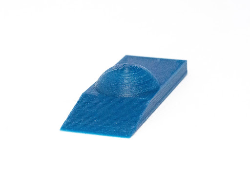
Figure 3: Notice the Roughness of the Finish Due to Layer Height Surface Angle
Vertical Surface Finish
Quality vertical surface finishes are a direct result of layer height, nozzle diameter and perimeter extrusion speeds. Increasing the number of perimeter layers would probably not affect the surface finish in the z-direction, but printer extrusion speed and layer height should be adjusted for the best finish. Also, take into account the type of source material that you are using when adjusting the extrusion speed and keep your layer heights between 100 - 200 microns. As always, post processing will enhance the surface finish of a quality part or end product (See Figures 4 - 6).
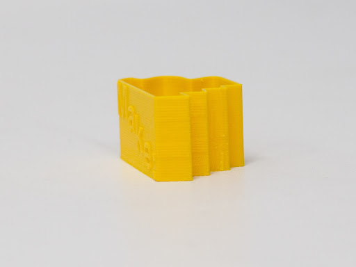
Figure 4: Notice That the Finish on Sharp Angles is Not as Smooth as on Curves
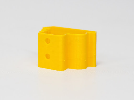
Figure 5: Curved Surfaces are Usually Smoother
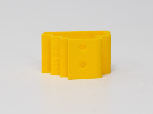
Figure 6: Angled and Curved Surfaces
Overhangs
Overhangs are the bane of designers and engineers when creating models for 3D printing. The prevailing guidance is either to position the part so there are no overhangs or to provide actual or 3D printed supports in the z-direction once printing begins. When 3D printing with overhangs, the best guidance to remember the 45 degree rule. Most printers can print overhangs up to 45 degrees with little issues, but angles up to 70 degrees may be achieved if you have your 3D printer dialed in (See Figure 7). Additionally a layer height reduction and a lower extrusion speed may assist in printing angles greater than 45 degrees. Another method of mitigating the overhang issue is to design in chamfers or fillets on the solid model. This will assist the printer in adjusting for the overhang gap. In the end, trial and error while adjusting layer height and extrusion speed will reveal the maximum overhang angle that your printer will be able to successfully mitigate.
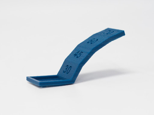
Figure 7: Notice the Roughness of the Finish at 60-Plus Degree Angles
Retraction Performance
Stringing is a visible and post processing nightmare. It is most often apparent when attempting to print more than one model or part simultaneously or when a model or part has large gaps or negative space. Stringing is a direct result of the retraction length and speed settings for a particular print (See Figure 8). However, do not be dismayed. A helpful reference guide on retraction and how to mitigate stringing may be found at Retraction: Just say "No" to Oozing.
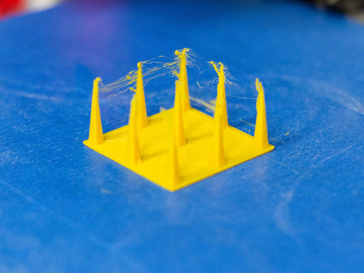
Figure 8: Example of Stringing Due to Retraction
Bridging
Bridges are printed flat sections that cross open spans in the model. Printing bridges is something of an “art” and many enthusiasts make videos of distances that they were able to span on their printers in a typical “can you beat that” bravado. With most bridges while printing at average speeds, a span of 50mm is common. However, some printers can do even longer spans and the length of the span may also be dependent on the type of material used. When bridging, keep the extruder speed between 20 - 30 mm/s. The default setting for bridges in MatterControl is 20 mm/s (See Figure 9). Just remember that the faster the speed, the greater the chances are for filament sags. Trial and error is the modus operandi for this process as you slowly synch your machine with the optimal materials and speeds.
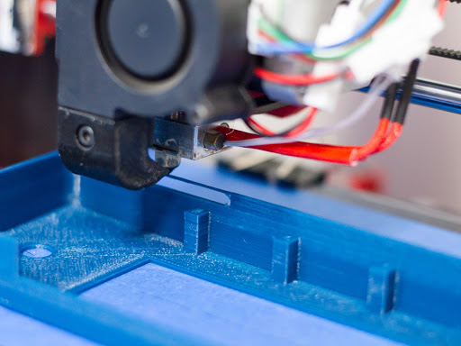
Figure 9: Example of Bridging
Negative Space Tolerance
Another thorn in the sides of designers and engineers is the negative space tolerance issue. This really comes into play when attempting to join prints or parts together into one assembly. Negative space dimensions are material specific and are affected by curing and surface finish. Many of these issues may be mitigated through design, but trial and error with your specific machine will usually provide you with a clear path forward (See Figures 10 and 11). For more information on this subject, feel free to refer to the reference article MatterHackers Lab: Design 3D Printed Assemblies.
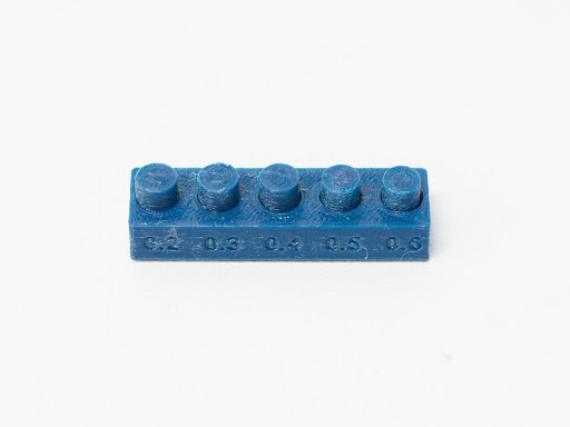
Figure 10: Negative Space Test Model With a Negative Space of .2 and .3mm
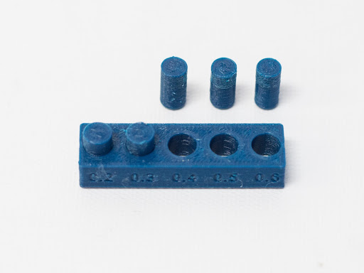
Figure 11: Notice That the Two Pins Printed Were Not Able to be Removed
Z-Wobble
Z-wobble is entirely a mechanical issue and is most likely caused by out-of-tolerance mechanical components and / or improper machine calibration (See Figure 12). It is prevalent with Cartesian type printers, especially those with dual z-axis ball screws. Cantilever stiffness also plays into the wobble phenomena as often Cartesian printers have a lot of “play” in the printer carriage itself. In order to mitigate this issue, make sure that your extruder and printer carriage are reasonably stiff and that the carriage traverses along the cantilever in a level manner. In other words, make sure that your machine is level and calibrated correctly. Some components over time will wear, so make sure that the screws / ball screws and bearings are maintained, lubricated and in good condition. If there has been some wear, you may want to replace the components. If you hear any grinding or sounds of friction, be sure to revisit component and bed leveling processes. The reference article How to Calibrate Your Extruder will lead you through the calibration process for extrusion.
The advent of Delta printers solves or at least mitigates the z-wobble issue. Z-wobble is practically eliminated on a Delta printer due to less weight on the extruder housing and in the use of three towers from which to suspend the extruder. Most Delta printers utilize the Bowden solution which keeps the extruder motor off of the carriage. This elegant solution has improved upon many of the issues associated with a standard Cartesian printer.

Figure 12: Example of Z-Wobble (Image courtesy of Danie Grobbelaar)
Support Material
If you have been 3D printing for a number of years, you will know and understand the challenges of adding and utilizing support material. Older slicing solutions were notorious for printing support material that was almost impossible to remove, with some supports actually adhering and melting to the part itself. Today’s controllers provide a support solution that is much easier to remove and often places “air gaps” between the actual part and the materials forming the supports. For a base setting in MatterControl, utilize the 10% infill setting of line patterns at 2.5mm intervals in generating supports. Also, include a raft (the article Printing with a Raft provides background information) with the supports to ensure that the support material adheres to the print bed. An “air gap” of .3mm is the default, but you may want to adjust this setting on an as needed basis. Feel free to increase the infill settings and decrease the intervals should you need more support throughout the model. The goal of supports is to provide enough material so that all facets of the model may be printed coupled with ease of removal of the support material once the print is finished. For those with dual extruder printers, you may want to utilize support filament to include HIPS and / or PVA in one of the two extruders while printing.
In summary, the quality of your 3D printed parts hinges just as much on understanding your machine’s tolerances and capabilities as it does on print bed leveling, machine component leveling, machine calibration and the design and positioning of the model / part for printing. Printing the Test Print Models on your machine with different materials and settings will ensure that you know your machine’s capabilities and where your tolerances may be adjusted. This like all good things in life will take time, so step back and enjoy the journey. You are a master creator and your skills and capabilities will produce unique parts and products for all to enjoy.